How To Draw Circles Using Triangles In Webgl
I recently had the opportunity to assistance implement some of the functionality of D3FC in WebGL. D3FC is a library which extends the D3 library, providing commonly used components to make it easier to build interactive charts.
D3FC was initially created using an SVG implementation. A Canvass implementation was subsequently added, which was by and large faster than SVG by an order of magnitude. It withal performs slowly, all the same, when handling more 10,000 points.
WebGL is a GPU accelerated 3D framework which provides a JavaScript API. By using this to render second graphics, we are hoping to render a few orders-of-magnitude faster than Canvas (for a demonstration of this, see Andy Lee's instance)
Running lawmaking on the GPU is significantly quicker than JavaScript, and so nosotros want to pass over every bit much work as possible.
How Does WebGL Work?
Everything rendered by WebGL is congenital using triangles. To construct these triangles, nosotros need to define two things - the locations of the vertices and the colour of the private pixels (or fragments) within the triangle.
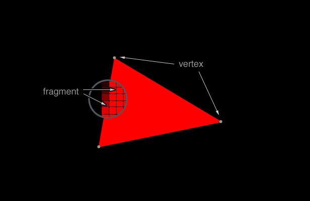
These triangles tin exist combined to generate detailed, 3D visualisations (check out this aquarium instance). However, we merely demand to worry near second environments, which removes a lot of the complication of WebGL. For case, we don't demand to worry about lighting or textures.
We define the vertices and the fragments using the creatively named vertex shader and fragment shader. The vertex shader is called for each vertex and sets the position of that vertex. Similarly, the fragment shader is chosen for each pixel and determines the colour of that pixel.
Our task, as the developers, is simple:
- Define the shaders.
- Pass the data and whatsoever other variables to the GPU with buffers.
- Hand our shaders to the GPU.
- Let the magic happen.
Sounds easy enough, but how do we do all this in do?
Making a simple D3FC component that renders to WebGL is quite like shooting fish in a barrel. We convert our series information to "triangles", load them into the buffers, and render them using elementary shaders. To maximise our performance, however, we want to minimise the number of triangles and motion equally much computation to the shaders as possible.
This web log explores ane approach to this process, looking at how to render round points with minimal data transferred across buffers and making best use of the shaders.
Cartoon squares
Because each shape has equal superlative and width, nosotros can perform most of the calculations in the fragment shader without too much waste material. Our vertex shader can render a foursquare large enough to contain the shape, and the fragment shader volition discard any pixels that aren't needed.
We need to calculate the length of the edges of the square, which we'll call vSize. Since we know the area nosotros want our symbol to fill, nosotros tin work backwards to summate vSize. For example, to calculate vSize for a circle:
attribute float aSize ; // The area of the shape varying float vSize ; // The length of the edge of the foursquare containing the shape vSize = 2 . 0 * sqrt ( aSize / 3 . 14159 ); // Summate the bore of the circle from the area We pass in aSize into the buffers, and our vertex shader uses this to calculate vSize. Because vSize is varying, it tin be passed to the fragment shader.
The vertex shader also needs to define ii variables - the point size (gl_PointSize) and the indicate's coordinates (gl_Position).
gl_Position is a vector with four components (vec4). The first iii components correspond the 10, y, and z coordinates of the signal. We'll pass the x and y coordinates in through the buffers. Since we're working in 2D infinite, nosotros don't have to worry about the z coordinate, so nosotros'll set it to 0.
The fourth component of gl_Position changes this point into a homogeneous coordinate. This is useful when manipulating 3D data. In our case though, we'll leave it as the default of one.
attribute bladder aXValue ; attribute float aYValue ; gl_Position = vec4 ( aXValue , aYValue , 0 , 1 ); gl_PointSize will be the length of the foursquare (vSize) plus whatsoever actress length added by the edge (we'll use this to add a "stroke" to the points later). Nosotros can meet what this extra length is by imagining the shape lying apartment with the edge as a separate layer above it.
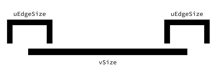
Each edge is one-half within the shape and half without. This means the indicate size becomes vSize + (0.5 * uEdgeSize) + (0.five * uEdgeSize), or vSize + uEdgeSize.
In theory, nosotros're done. In practise, however, at that place's 1 more thing we need.
The value we merely calculated is continuous. Notwithstanding, nosotros'll be drawing to detached pixels. This, in improver to only using an approximate value for pi and floating-betoken errors, tin can pb to aliasing.
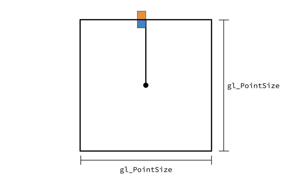
If 1 of our shape's outer pixel is less than gl_PointSize (the bluish pixel), then it will render fine. Withal, if the outer pixel is merely outside gl_PointSize (the orangish pixel), and then it will be cut off. To preclude this, we'll add 1 to our gl_PointSize to ensure the shape's outer pixels are always rendered.
uniform bladder uEdgeSize ; gl_PointSize = vSize + uEdgeSize + one . 0 ; Put this all together, and we have a vertex shader drawing our correctly sized shapes.
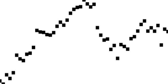
So far our circles are looking quite… not round. Then allow'south jump over to the fragment shader and find the statue hidden in the marble.
Cartoon circles
For each pixel of the square, we demand to determine whether it is within the shape and if not, discard the pixel. For a circle, this is straightforward - we summate the distance from the pixel to the eye.
The vertex shader transforms our coordinates into a different coordinate organisation called clip infinite. Clip infinite is a cube that is two units wide and contains the points from ane corner (-1, -1, -ane) to other (1, 1, 1).
To convert our points to clip space, we can apply gl_PointCoord. gl_PointCoord gives usa the two-dimensional coordinates of the betoken, ranging from 0.0 to 1.0 in both directions. Therefore, to convert gl_PointCoord to clip space, we can use (2.0 * gl_PointCoord) - 1.0.
Once we map our point to prune space, nosotros can discard any pixels which have a greater distance to (0, 0, 0) than 1. To calculate the distance, we can use length, which will summate the length of the vector (or, in other words, the distance from the point to the origin).
varying bladder vSize ; float altitude = length ( ii . 0 * gl_PointCoord - 1 . 0 ); if ( distance > one . 0 ) { discard ; } 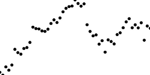
That's more than similar information technology! Instead of black circles, though, it'd be overnice to be able to decorate the points - modify the colour, add a border, etc.
Decorating circles
Changing the colour is uncomplicated. We pass the colour into the buffers and then set gl_FragColor to that colour in the fragment shader.
uniform vec4 uColor ; gl_FragColor = uColor ; Adding the border is more complicated. We need to calculate whether the pixel we're looking at is on the edge and, if it is, colour the pixel the edge colour. Sounds simple but a lot is going on hither and so let's suspension information technology down.
Nosotros create a variable chosen sEdge, which will be a bladder between 0.0 and 1.0. When sEdge is 0.0, we proceed the existing gl_FragColor. When it is 1.0, nosotros set gl_FragColor to uEdgeColor, which is passed in through the buffer. Whatever number in between will result in a blend between the two colours.
How practice nosotros summate sEdge? Information technology'south easier to see what's happening in 1D. Imagine a line beingness fatigued from the centre of the shape to the edge. Part of that line will exist the shape colour and part will be the edge colour. We demand a part that will prepare sEdge to 0.0 at the points of the line where it should be the shape colour, 1.0 at the edge and a number in between during the transition betwixt the two. We'll use the intermediate numbers to smooth the transition. This reduces the aliasing that can occur when square pixels try to represent a curved border.

Fortunately, WebGL provides us with that role. smoothstep takes three arguments: edge0, edge1 and x.
- If
xis less thanedge0, the part returns 0.0. - If
xis greater thanedge1. the function returns 1.0. - If
tenis in betweenedge0andedge1, the function returns a number betwixt 0.0 and 1.0, using a Hermite polynomial.
We're nearly in that location - we at present need to figure out what edge0, edge1 and ten are.
edge1 is where the edge starts, so it is vSize - uEdgeSize.
edge0 is where the colour transition starts, so it is edge1 minus the size of the "transition gap" (where the sEdge is transitioning from 0.0 to 1.0). The greater we set this number, the greater the smoothing of the transition between the shape color and the edge colour. A smaller number increases the sharpness of the transition simply also increases the probability of aliasing.

two.0 removes the aliasing while maintaining the sharp line that we want, so we'll fix edge0 as vSize - uEdgeSize - 2.0.
Considering we previously represented altitude in clip infinite, it is a number between 0 and one. We tin use this number as the fraction of the total distance of the pixel from the centre to the border of the shape. For instance, if altitude = 0.v, the pixel is halfway between the centre and the edge. Thus, to summate where the pixel is, we demand to multiply distance past the point size. This gives us ten = distance * (vSize + uEdgeSize).
Put all this together, and we have our answer!
uniform vec4 uEdgeColor ; uniform float uEdgeSize ; float sEdge = smoothstep ( vSize - uEdgeSize - two . 0 , vSize - uEdgeSize , distance * ( vSize + uEdgeSize ) ); gl_FragColor = ( uEdgeColor * sEdge ) + (( 1 . 0 - sEdge ) * gl_FragColor ); 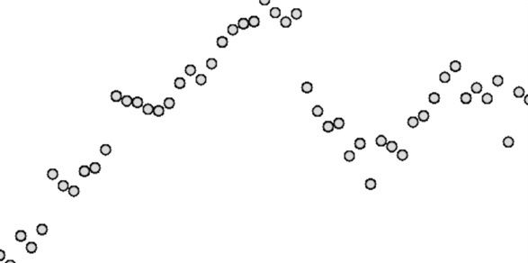
Ok, we're well-nigh done, there's one last thing to handle. If you look closely at the edges of the circles, you can see they're still jagged. And so our concluding step is to implement some anti-aliasing.
Anti-aliasing circles
We'll use a similar technique every bit earlier, but instead of smoothing the shape colour into the border, nosotros'll smooth the edge colour into the background. We'll choose a transition size of 2.0 for the aforementioned reasons as before.
gl_FragColor . a = gl_FragColor . a * ( 1 . 0 - smoothstep ( vSize - 2 . 0 , vSize , distance * vSize )); 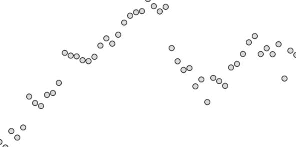
And we're done!
Other shapes
Although we've used circles as an example, the same principles utilise for any shape. All that needs to be adapted are the calculations for vSize and distance.
In the case of other shapes, distance won't exist the actual distance just a number which is greater than one.0 but for the pixels which lie outside the shape. For instance, altitude for a foursquare could be calculated with:
vec2 pointCoordTransform = 2 . 0 * gl_PointCoord - one . 0 ; bladder altitude = max ( abs ( pointCoordTransform . x ), abs ( pointCoordTransform . y )); Here we once again convert gl_PointCoord to prune space. We take the maximum accented value of the x and y coordinate. In this mode, if either the 10 or y coordinate is greater than 1.0 (or less than -1.0), we know information technology is outside of the foursquare and can be discarded.
Decision - Why are we doing this again?
Using this approach has plenty of advantages.
GL_POINT works well when drawing a large number of modest 2D items. If we used GL_TRIANGLE_STRIP, for example, we'd accept to calculate how to draw each shape using triangles. Using each vertex equally a point means nosotros don't have to worry about geometry.
In addition, procedural rendering of the shape in the fragment shader is fast. It also still allows changes in size without resulting in scaling artifacts.
Source: https://blog.scottlogic.com/2019/10/17/sculpting-shapes-with-webgl-fragment-shader.html
Posted by: swanmencir.blogspot.com


0 Response to "How To Draw Circles Using Triangles In Webgl"
Post a Comment